2.1. Problem
- Three missionaries and three cannibals must cross a river.
- They cross the river using a boat which can carry at most two people.
- On each side of the river, cannibals must not outnumber missionaries, otherwise cannibals will eat missionaries.
| Order | Left | Boat | Right |
| 0 | MMM CCC | ||
| 1 | MMMC | CC -> | CC |
| 2 | MMMCC | <- C | C |
| 3 | MMM | CC -> | CCC |
| 4 | MMMC | <- C | CC |
| 5 | MC | MM -> | MM CC |
| 6 | MMCC | <- MC | M C |
| 7 | CC | MM -> | MMM C |
| 8 | CCC | <- C | MMM |
| 9 | C | CC -> | MMM CC |
| 10 | CC | <- C | MMM C |
| 11 | CC -> | MMM CCC |
Implement sequential logic of the problem
- Input: clock (1bit), reset (1bit), (no direction) _ You have to create direction internally
- Output: next state (left side of the river, 4bit), finish (1bit)
- internal register: current state (4bit), direction (1bit)
- If reset is 1, current state and direction should change to initial state and initial direction (asynchronous)
- Finish is set if and only if next state is final state
- If current state (including direction) is final state, next state should be initial state (including direction)
- If current state and direction is far from any solution, next state should be initial state (including direction)
Top module name: missionary_cannibal
- Input : reset, clock (each 1 bit)
- Output1: 2bit (output [1:0] missionary_next)
- Output2: 2bit (output [1:0] cannibal_next)
- Output3: 1bit (output finish)
N-bit register
- N-bit register can be implemented with # of D-flip flop.
- You can utilize given D-flip flop to implement your N-bit register
- Input of given D-flip flop is clk, reset, and data (D)
- Output of given D-flip flop is Q

2.2. Project summary
Practice truth table on description of the situation. (By, PPT 4page)
The above situation is perhaps the best way to solve the problem. We can write the whole truth table based on TABLE 1. The new truth table is prepared as close to TABLE 1 as possible. However, when writing a truth table, we should be careful about the second limiting condition of the problem and the direction away from solving the problem.
After writing the truth table, set up a Boolean function expression for the output based on the truth table. Where Boolean function expressions are written for implementation in the gate level as much as possible.(By, PPT 5page Project Specification – clause 5)
When the boolean function expression is completed, make a module(Verilog code) in ModelSim and test it using the appropriate input script. A suitable input script will be provided by the truth table. What is important is to implement a combinational logic circuit with five inputs and four outputs.
2.3. Module decription (Include description of implement)
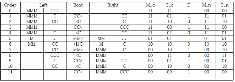
2.3.1. Truth table
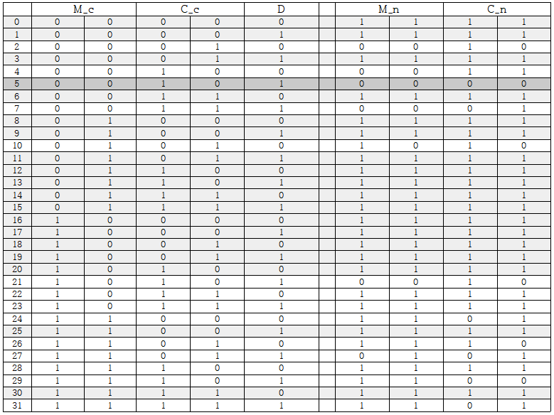
Shaded parts of the truth table will be described in more detail on the next page.
missionary_curr : a variable that stores the number of missionary at the starting point in binary.
cannibal_curr : a variable that stores the number of cannibal at the starting point in binary.
direction : Left is 0 and right is 1
missionary_next : a variable that stores the number of missionary at the destination in binary.
cannibal_next : a variable that stores the number of cannibal at the destination in binary.
2.3.2. Input and output

The program receives the current status of missionaries and cannibals and direction as input.
M_c : Missionaries_current state, C_c : Cannibals_current state, D : Direction

The program outputs the following states of the missionaries and cannibals.
M_n : Missionaries_next state, C_c : Cannibals_next state
2.3.3. Explanation of special cases

This situation is that the current situation is far from the solution and either reset the state or it has already been resolved and reset the state. (By, PPT 5page Project Specification – clause 3, 4)

This situation is that everyone has moved to the other side of the river. If this situation enters the input, the value will be initialized by line 1 and line 2 of the truth table.
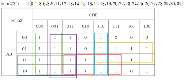
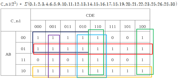
2.3.4. Boolean function expression
M_c, M_n, C_c and C_n are 2-bit bundles, but for convenience, they are spelled M_c1, M_c2.
(That is, M_c is
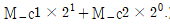
)
It is marked A,B,C,D,E again in order.

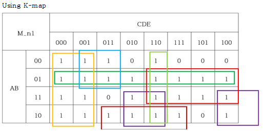
= A'B + AE' + BC + C'D' + A'C'E + CDE' + AB'D
In addition to the K-MAP method, this can be simplified in the same way in accordance with several rules on boolean function about simplification.
= C'D' + C'E + CDE' + AE' + AD + BC
= A'B + AB' + C'D'E + DE' + CE' + A'C'
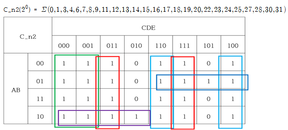
= C'D' + CE' + DE + A'BE + AB'C
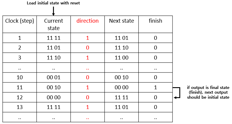
2.3.5. Conceptual table
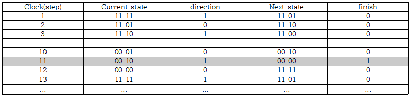
If output is final state(finish), next output should be initial state
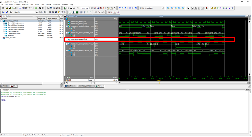
Considering clk, finish is expected to be about 20 to 1, which is about twice as much as 11.
I will actually check this through modelsim simulation.
The red box highlighted in SCREENSHOT 2. Simulation (Modelsim) of this report confirms that the finish has spread to 1 at 19ns-20ns. This value appears again at 43ns-44ns. Through this, we can see that the finish becomes 1 and the next state is initialized and the solution is repeated again. (In fact, 19ns are curled up with yellow lines.)
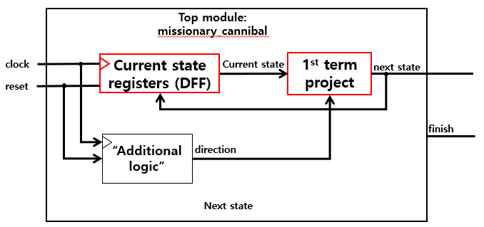
2.3.6. D flip-flop for proper status update and outline planning
Implement sequential logic of the problem.
Top module name: missionary_cannibal
Input : reset, clock (each 1 bit)
Output1: 2bit (output [1:0] missionary_next)
Output2: 2bit (output [1:0] cannibal_next)
Output3: 1bit (output finish)
We input only the clocks and resets into the circuit. Here, write a script with the note that the clock continuously reverses the value in 1ns units, and only briefly changes it when initializing the value in resets. Therefore, the values for all other states and directions should be automatically adjusted by constructing a separate circuit. (By, 2’nd Term PPT 5page Project Specification – clause 1 Input: clock (1bit), reset (1bit), (no direction))
Only the 1bit variable associated with termination and the following conditions correspond to the output. Therefore, the most recent state is the internal storage variable, which is used to update the new state appropriately according to the clock variable. (By, 2’nd Term PPT 5page Project Specification – clause 2, 3, 4 and 5 (Output: next state (left side of the river, 4bit), finish (1bit) / internal register: current state (4bit), direction (1bit) / If reset is 1, current state and direction should change to initial state and initial direction (asynchronous) / Finish is set if and only if next state is final state / If current state (including direction) is final state, next state should be initial state (including direction))
The important thing is that once we get away from the final solution, we have to reset the condition. This is already reflected in the module of the first project as described in the tutorial video. Therefore, it is not necessary to consider the above constraints in constructing additional circuits. (By, 2’nd Term PPT 5page Project Specification – clause 7 If current state and direction is far from any solution, next state should be initial state (including direction))
We may be able to optimize a little more through state reduction.
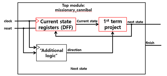
The above circuit is a schematic diagram from the tutorial video. (By, 2’nd Term PPT 9page Project Specification)
We will implement this circuit through velilog coding.
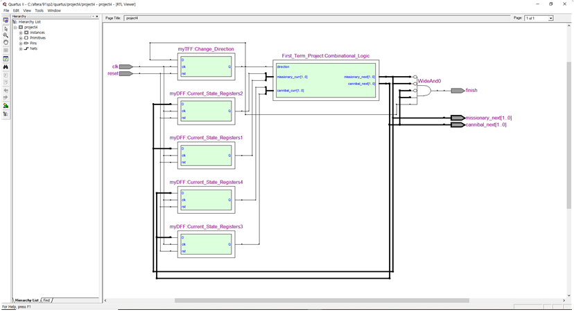
Results for this can be found in SCREENSHOT 5. RTL Viewer (Quartus) of this report. We can see that four d flip-flops are arranged in parallel to update the status according to the clock and that t flip-flop determines the direction.
2.3.7. T flip-flop for proper direction update
We have to create direction internally. (By, 2’nd Term PPT 5page Project Specification – clause 1_1)
We'll have to think about a turnabout. Turning around requires a separate logic, but in tutorial videos, 010101... Or 101010...repeated with Here we can see that we have a close relationship with the clocks. However, if the clocks are used as they are, the proper condition will cause a change of direction before the updates are made. That is, after one cycle of the last updated clock, the direction should be changed, and the appropriate sequential logic is t flip-flop.
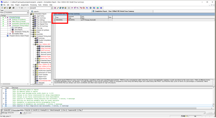
2.3.8. fMax(Max frequency)_Result
436.68MHz
See SCREENSHOT 4. fMax (Quartus) in the "4. simulation Screenshot_Result" of this report for evidence of the above values.
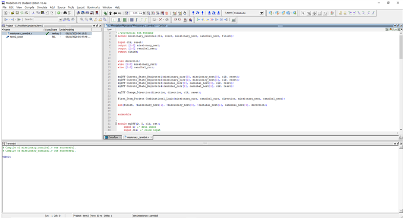
2.4. HDL code (Include program comment)
//COSE221 : Term project2 : Missionaries and cannibals problem
//2019320121 Son Hyegang
module missionary_cannibal(clk, reset, missionary_next, cannibal_next, finish);

input clk, reset;
output [1:0] missionary_next;
output [1:0] cannibal_next;
output finish;

wire direction;
wire [1:0] missionary_curr;
wire [1:0] cannibal_curr;

//updated status, myDFF (Q, D, clk, rst) defines the next state variable : input, the la curr state variable : output.
//We should repeat this as the input size of First_Term_Project (mission_curr, cannibal_curr, direction, mission_next, cannibal_next). That is, four flip-flops are required.
myDFF Current_State_Registers1(missionary_curr[0], missionary_next[0], clk, reset);
myDFF Current_State_Registers2(missionary_curr[1], missionary_next[1], clk, reset);
myDFF Current_State_Registers3(cannibal_curr[0], cannibal_next[0], clk, reset);
myDFF Current_State_Registers4(cannibal_curr[1], cannibal_next[1], clk, reset);

//t flip-flop updates directions periodically according to the lock
myTFF Change_Direction(direction, direction, clk, reset);

//In the First_Term_Project (missionary_curr, cannibal_curr, direction, mission_next, cannibal_next), it is important that the output of the flip-flop should be input.
First_Term_Project Combinational_Logic(missionary_curr, cannibal_curr, direction, missionary_next, cannibal_next);

//Finish can be 1 when the next status is 00 00.
and(finish, !missionary_next[1], !missionary_next[0], !cannibal_next[1], cannibal_next[0], direction);

endmodule

//Classical positive-edge-triggered D flip-flop
//The D flip-flop captures the value of the D-input at a definite portion of the clock cycle (such as the rising edge of the clock).
module myDFF(Q, D, clk, rst);
    input D; // data input
    input clk; // clock input
    input rst; // synchronous reset
    output reg Q;

    always @(posedge clk or posedge rst)
    begin
        if(rst == 1'b1)
            Q = 1'b0;
        else
            Q = D;
    end
endmodule

//T flip-flop
//If the T input is high, the T flip-flop changes state ("toggles") whenever the clock input is strobed. If the T input is low, the flip-flop holds the previous value.
module myTFF(Q, D, clk, rst);
    output Q;
    input D, clk, rst;
    reg Q;

    always @ (posedge clk or posedge rst)
    begin
        if(rst) Q = 1'b0;
        else Q = !D;
    end
endmodule


module First_Term_Project(missionary_curr, cannibal_curr, direction, missionary_next, cannibal_next);

    //input
   //[1:0] a two-bit bus
   input [1:0] missionary_curr;
   input [1:0] cannibal_curr;
   input direction;

   //ouput
   output [1:0] missionary_next;
   output [1:0] cannibal_next;

    //wire : Mediation unit for connection to another gate (simple physical connection line)
   //These declarations help readability. A is more intuitive and convenient than Missionary_curr[0].
   wire nA, nB, nC, nD, nE, A, B, C, D, E;

    buf (A, missionary_curr[1]);
   buf (B, missionary_curr[0]);
   buf (C, cannibal_curr[1]);
   buf (D, cannibal_curr[0]);
   buf (E, direction);

   not (nA, missionary_curr[1]);
   not (nB, missionary_curr[0]);
   not (nC, cannibal_curr[1]);
   not (nD, cannibal_curr[0]);
   not (nE, direction);

   //missionary_next[1]
   wire m_n11, m_n12, m_n13, m_n14, m_n15, m_n16, m_n17;
   and (m_n11, nA, B);     //A'B
   and (m_n12, A, nE);     //AE'
   and (m_n13, B, C);      //BC
   and (m_n14, nC, nD);    //C'D'
   and (m_n15, nA, nC, E); //A'C'E
   and (m_n16, C, D, nE);  //CDE'
   and (m_n17, A, nB, D);  //AB'D

   //A'B + AE' + BC + C'D' + A'C'E + CDE' + AB'D
   or (missionary_next[1], m_n11, m_n12, m_n13, m_n14, m_n15, m_n16, m_n17);


   //missionary_next[0]
   wire m_n21, m_n22, m_n23, m_n24, m_n25, m_n26;
   and (m_n21, A, nE);     //AE'
   and (m_n22, A, D);      //AD
   and (m_n23, B, C);      //BC
   and (m_n24, nC, nD);    //C'D'
   and (m_n25, nC, E);     //C'E
   and (m_n26, C, D, nE);  //CDE'

   //C'D' + C'E + CDE' + AE' + AD + BC
   or (missionary_next[0], m_n21, m_n22, m_n23, m_n24, m_n25, m_n26);


   //cannibal_next[1]
   wire c_n11, c_n12, c_n13, c_n14, c_n15, c_n16;
   and (c_n11, nA, B);     //A'B
   and (c_n12, A, nB);     //AB'
   and (c_n13, nC, nD, E); //C'D'E
   and (c_n14, D, nE);     //DE'
   and (c_n15, C, nE);     //CE'
   and (c_n16, nA, nC);    //A'C'

   //A'B + AB' + C'D'E + DE' + CE' + A'C'
   or(cannibal_next[1], c_n11, c_n12, c_n13, c_n14, c_n15, c_n16);


   //cannibal_next[0]
   wire c_n21, c_n22, c_n23, c_n24, c_n25;
   and (c_n21, nC, nD);     //C'D'
   and (c_n22, C, nE);      //CE'
   and (c_n23, D, E);       //DE
   and (c_n24, nA, B, E);   //A'BE
   and (c_n25, A, nB, nC);  //AB'C'

   //C'D' + CE' + DE + A'BE + AB'C'
   or(cannibal_next[0], c_n21, c_n22, c_n23, c_n24, c_n25);
endmodule
2.5. Simulation Screenshot_Result
'학부공부 > Logic Design & Computer Architecture' 카테고리의 다른 글
| 8. ARM 5stage pipeline report 2 [Computer Architecture] (0) | 2021.12.02 |
|---|---|
| 7. ARM 5stage pipeline report 1 [Computer Architecture] (4) | 2021.12.02 |
| 6. ARM instruction 분석 report [Computer Architecture] (0) | 2021.12.02 |
| 3. Project 3_Calculator [Logic Design] (0) | 2021.12.02 |
| 1. Project 1_Missionaries and cannibals problem [Logic Design] (0) | 2021.12.01 |


댓글